Atari Lynx Vault is free, ad-free, and community-supported — please consider donating.
This site takes real effort to maintain. Your donation helps keep the lights on and the Lynx legacy alive.
via PayPal · any amount helps

The Atari Lynx supports cartridge sizes of 129K, 256K, 512K and 1Mb (bank switched). The Lynx cannot address data on the cartridge directly and instead uses two counters to read data. The first counter is for the block number (0 - 255), the second counter is for the position within the block (0 - 4095, depending on cartridge size). Your code must know the exact block size used on a cartridge to be able to read data from it.
Related pages:
Pin pitch: 1.59mm
Below is the pinout for a typical Atari Lynx Cartridge.
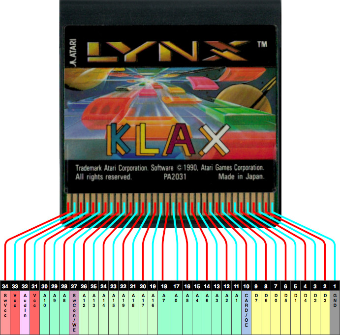
| 1 — GND 2 — D3 3 — D2 4 — D4 5 — D1 6 — D5 7 — D0 8 — D6 9 — D7 10 — CARD/OE 11 — A1 12 — A2 | 13 — A3 14 — A6 15 — A4 16 — A5 17 — A0 18 — A7 19 — A16 20 — A17 21 — A18 22 — A19 23 — A15 24 — A14 | 25 — A13 26 — A12 27 — SWCON/WE 28 — A8 29 — A9 30 — A10 31 — Vcc 32 — AUDIOIN digital I/O for 1M cards 33 — Vcc 34 — SWVCC |
Pins A12 - A19 are connected to the 74HC164 to select the block.
Pins A0 - A10 are connected to the 4040 to select the position within the block.
Pin A11 is missing.
The Card/OE pin is strobed on reads.
The Swcon/WE pin is strobed on writes.
Original information retrieved from RetroIsle.
SWVCC is an unregulated 5V supply as compared to VCC. This can be taken advantage of to measure the voltage level in the battery if a custom cart was made. The voltage on SWVCC would be Vbatt-5V-0.6V. Note that even when the Lynx is off, there is a small voltage present on both SWVCC and VCC pins at the cart connector.
♥ Did we get something wrong or you have something to contribute? Please tell us about it!
♣ We're looking for content editors and maintainers, if you want to help us out, let us know!