Atari Lynx Vault is free, ad-free, and community-supported — please consider donating.
This site takes real effort to maintain. Your donation helps keep the lights on and the Lynx legacy alive.
via PayPal · any amount helps

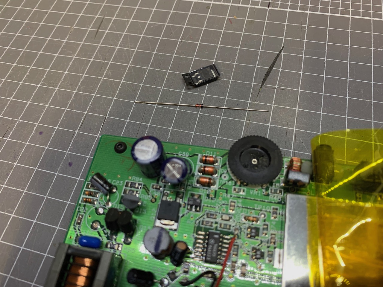
The MOSFET/Zener diode can fail in your Lynx, causing 9V to go into the CPU, effectively frying it. Since these components are used in a high frequency switching circuit to reduce the 9V input to a level of 5V, they can wear out over time. It's always a good idea to replace these two parts before powering up any new Lynx in your possession. Replacement MOSFET and Zener kits are available from the K-Retro Gaming Online store.
Lynx model 1 and 2 can use the same parts, however the part names and locations are in different places on the motherboard. The detailed guide is for the model 2, but the same steps apply to model 1 once you have located the components to replace.
Lynx 2 uses the following component names:
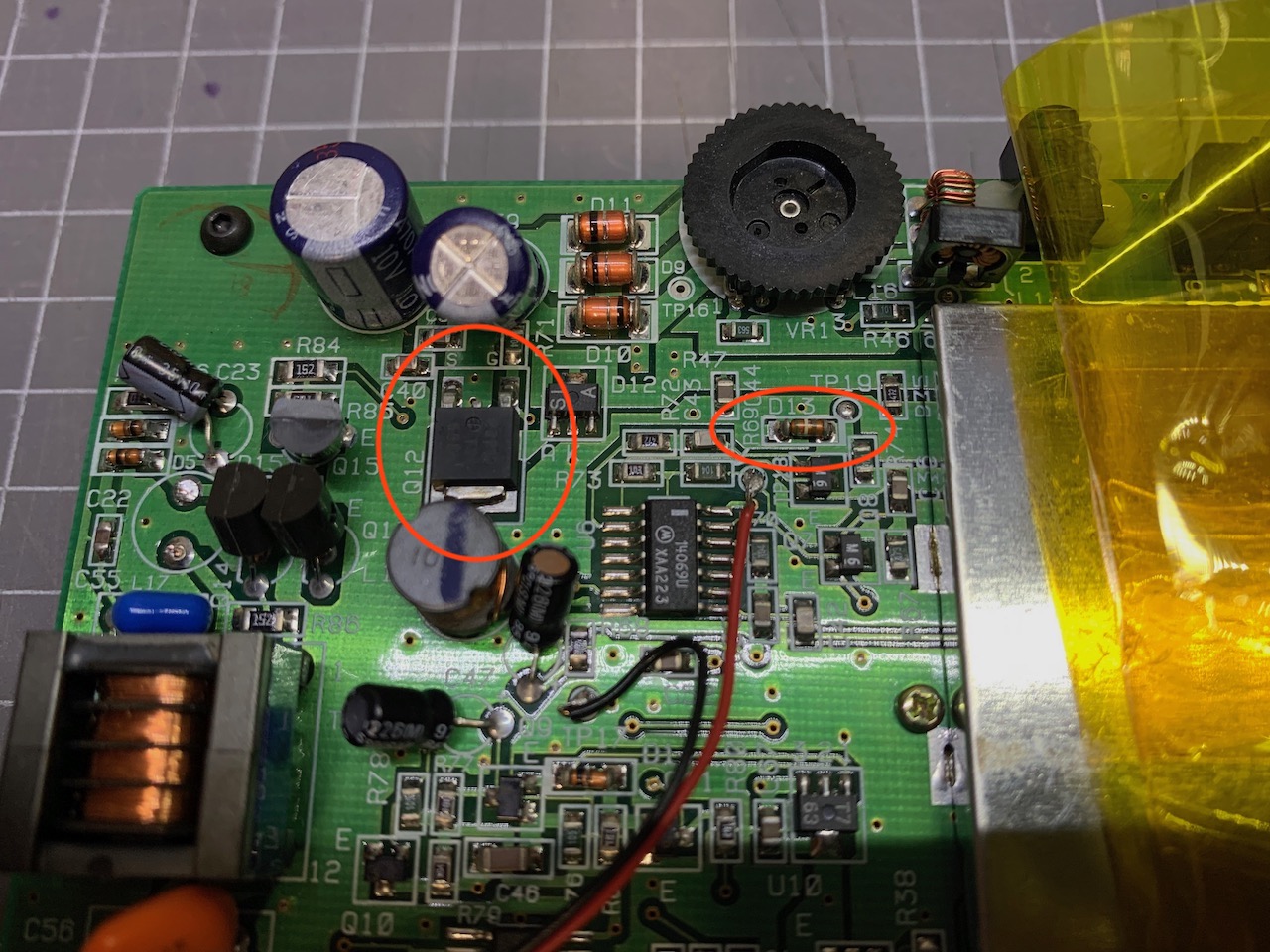
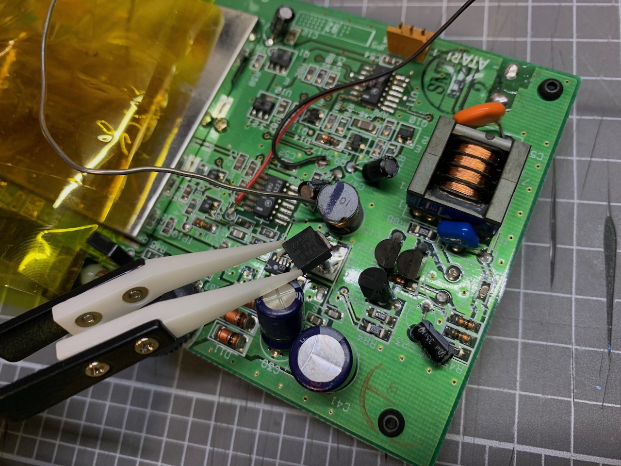
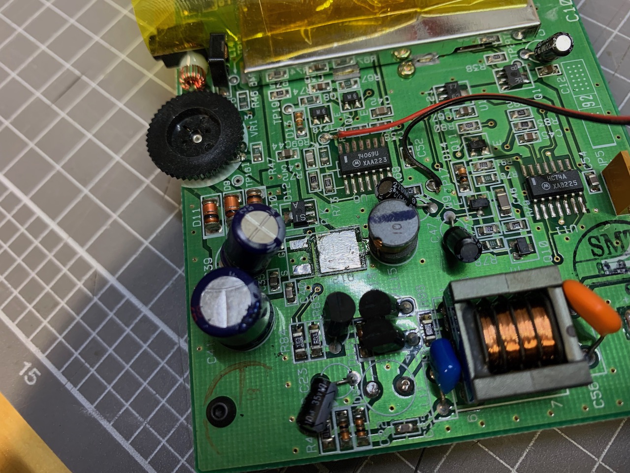
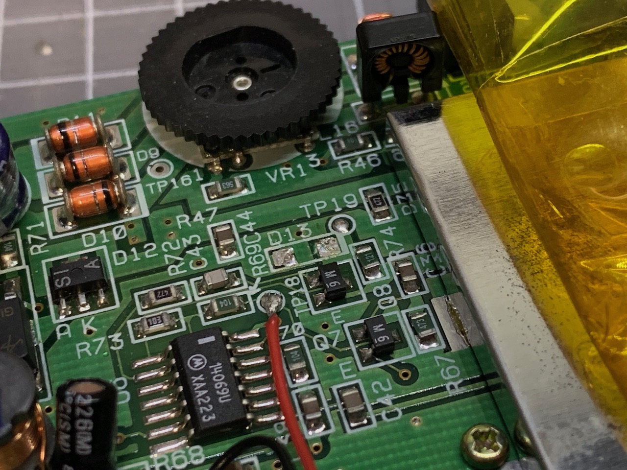
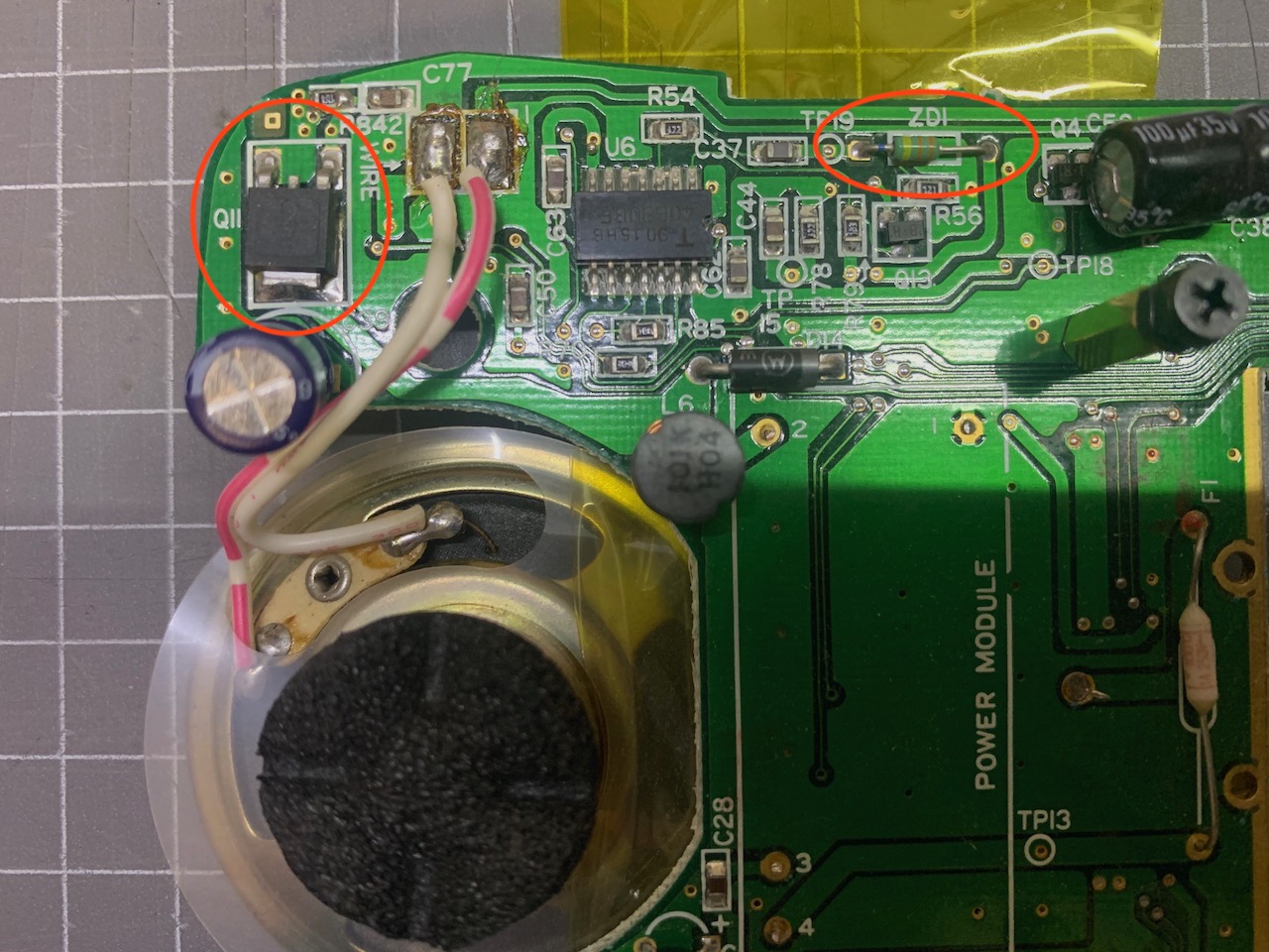
The MOSFET is located below the C39 capacitor on the top left section of the motherboard. It should be easy to spot. The zener is to the right of the MOSFET and directly under the brightness adjustment wheel.
 |  |
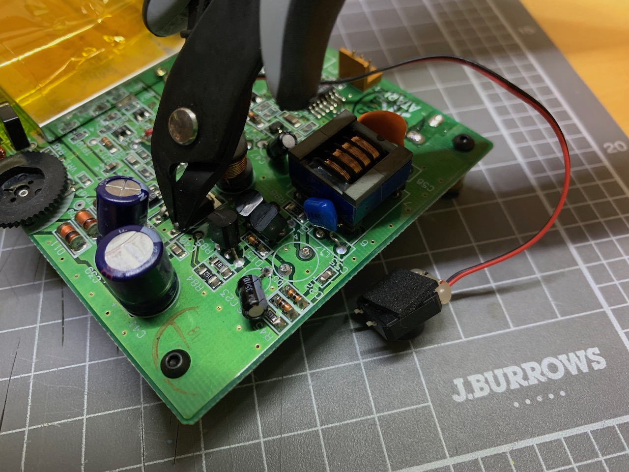
Using side cutters, snip off the thin legs on the MOSFET. This will let you desolder it much easier. You should have two clean cuts through these two legs. When clipping the legs off of the MOSFET try and clip them near the top of the legs where they go into the package. This way, you are putting less stress on the lower portion of the legs and pads this way.
NOTE: Use small, sharp side cutters for this. If you use larger side cutters, you can rip the solder pads off the PCB. If you don't have access to small side cutters, use solder wick to soak up as much solder around the legs as possible and then heat each leg, lifting it slightly in turn until there's no more contact with the motherboard.
 |  |
Now you can apply heat with a soldering iron on the drain (the big metal tab at the top). Once solder under the tab melts, the MOSFET should be easy to pull out with tweezers. Clean up any excess solder left on the pads using some solder wick.
 |  |
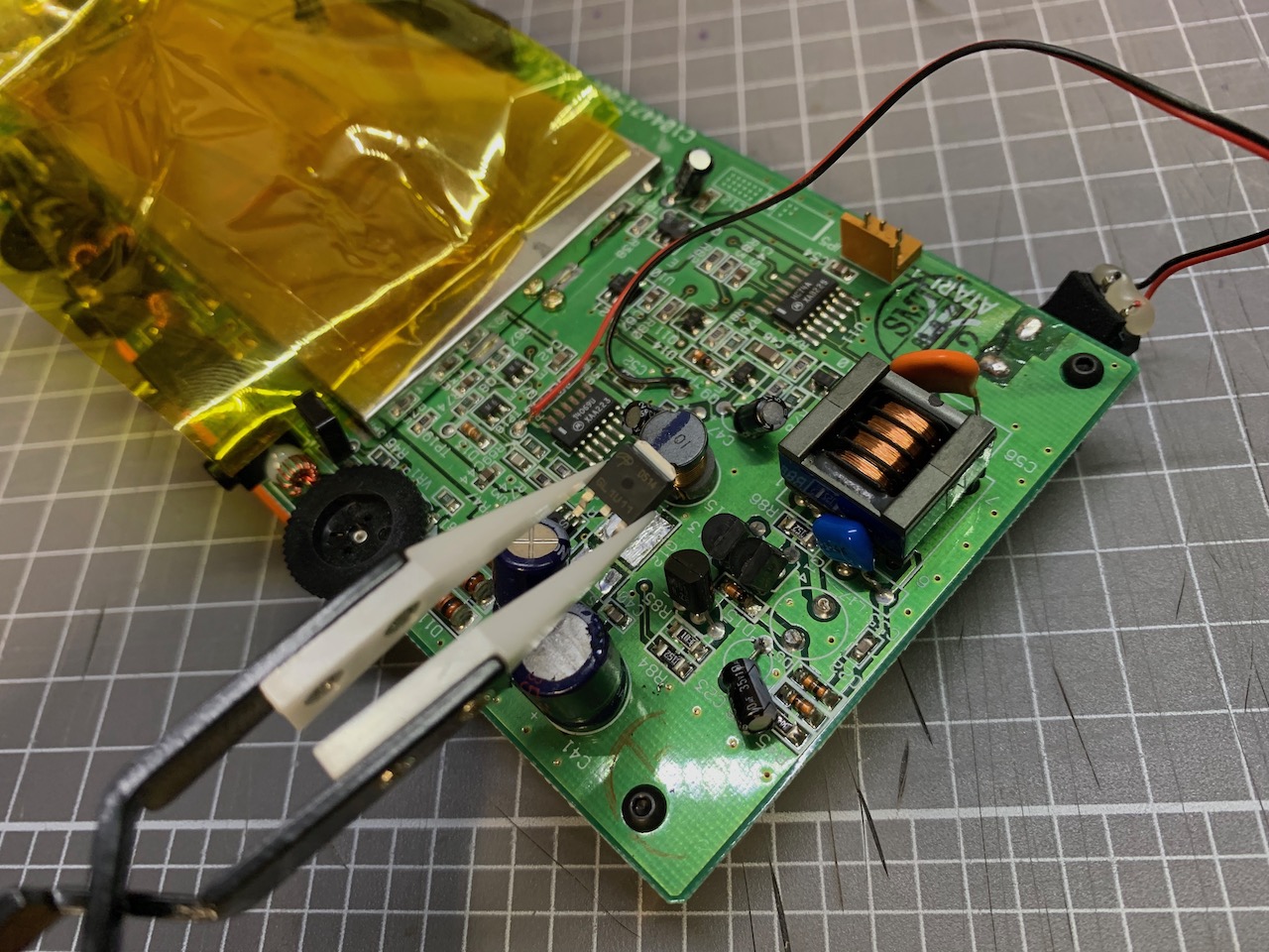
Position the new MOSFET into its home and solder it in. It's usually easier to solder one of the two legs first, then the tab at the top. The tab requires a bit more heat due to its size so having the component secured by one leg will make your job easier.
 | 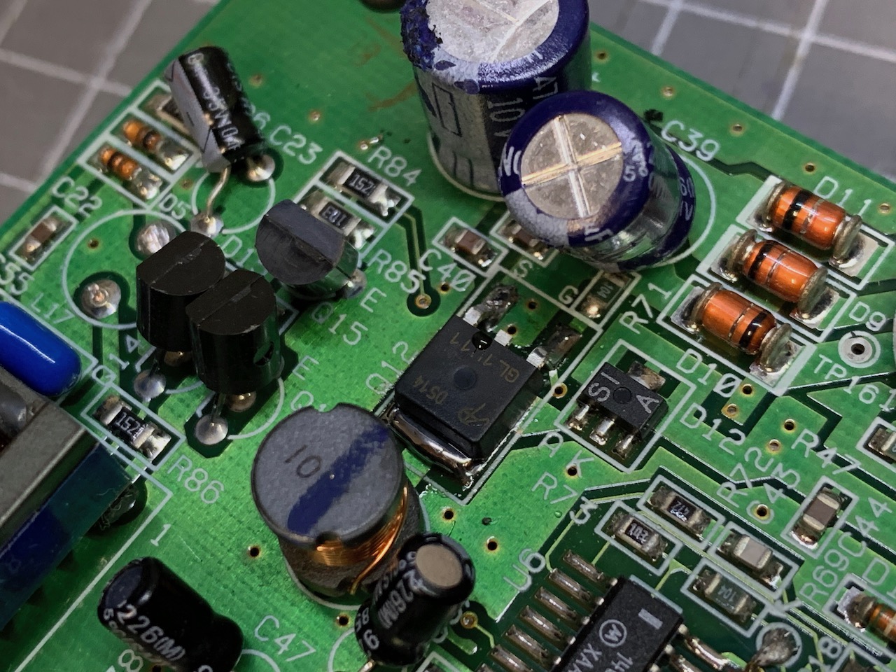 |
It can be a little tricky to remove this zener as it's an SMD part. Start with heating up one side with a soldering iron and using solder wick to remove as much solder as you can, repeat on the opposite side. If the zener is still attached, heat one side and gently lift that side a fraction of a millimetre. Don't lift it fully as that may strip the solder pad on the opposite end. Now heat the opposite end and lift that slightly too. After another 1 or two passes of doing this heat and lift cycle, one side should not have any more contact with the motherboard. You can now heat up the opposite end of the zener and it can be lifted off the motherboard.
Another trick to removing the SMD zener is to simply get a nice glob of solder on your iron so that you can make contact with both sides at the same time and then slide the zener off sideways from the pads.
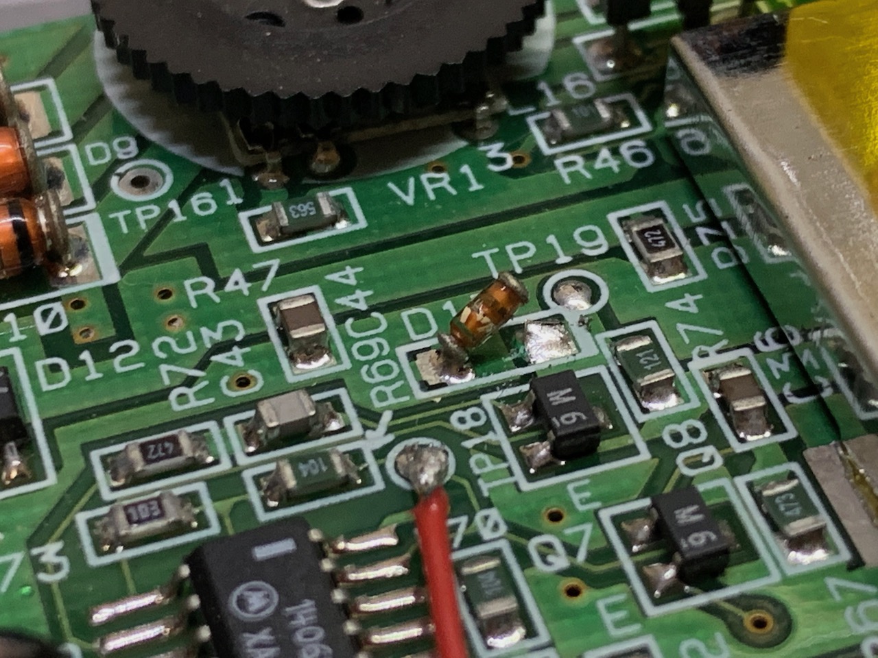 |  |
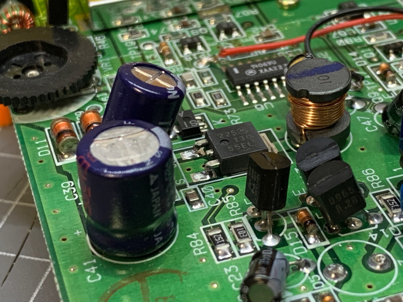
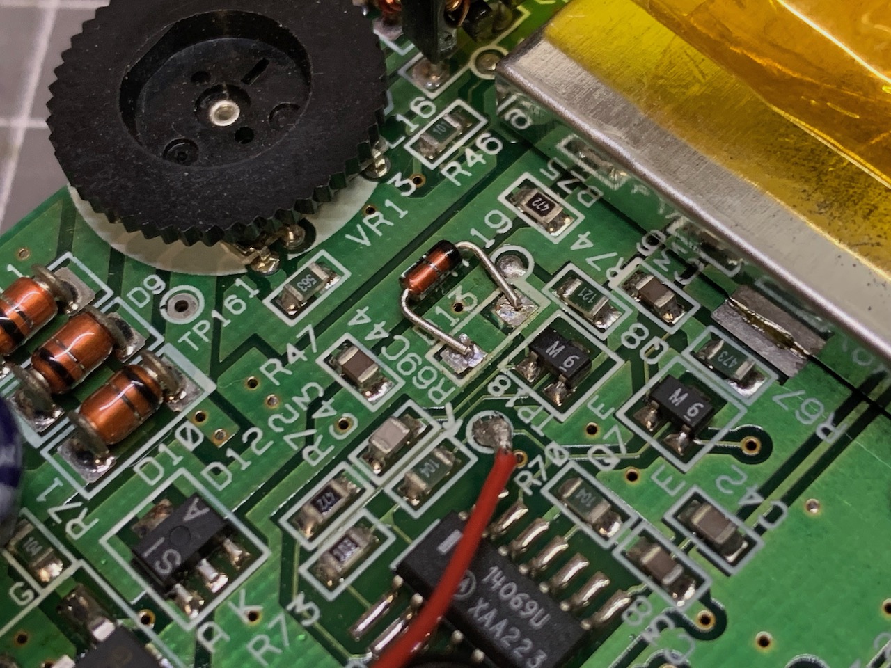
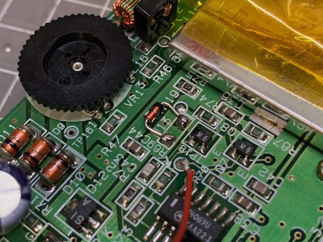
Since the original zener is an SMD part and the replacement is a through-hole component, you need to bend the legs of the new zener and cut them to size so it can fit across the D13 solder pads. Position the zener so that the black stripe is towards the RF shield/R74 resistor. Solder one leg, then the other.
Note: You can cut the legs off directly under the body of the zener diode and solder it on like an SMD part, do this by placing a blob of solder on one of the pads on the motherboard, hold the zener, melt the solder and position the zener in place. Solder the other pad and then re-touch the solder on the first pad. This way the zener looks much neater and almost indistinguishable from the original.
 |  |
Lynx 2 uses the following component names:
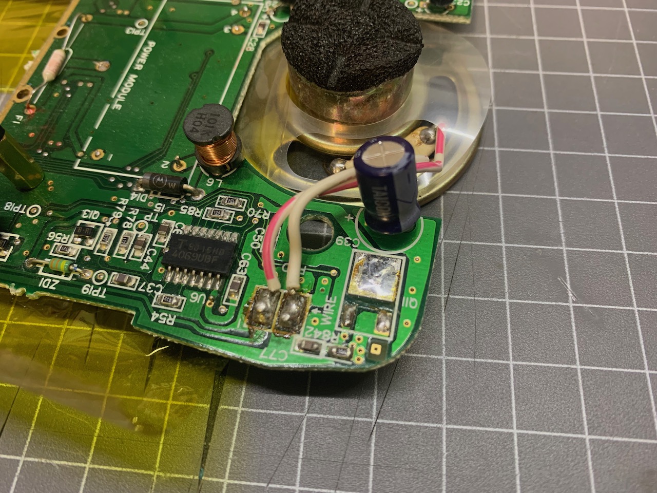
On the Lynx 1 motherboard the MOSFET is located on the top left section, above the speaker. The zener is to the right of it between TP19 and Q4 - along the top edge of the motherboard.
Follow the same process to remove the MOSFET as on the Lynx 2 (see steps above). With the zener, you can snip off the legs as close to the motherboard surface as possible, then heat up the holes and using solder wick remove all solder and the remaining portion of the leg. You should have two clean solder holes after this is done.
 |  |
The zener is installed with the black stripe towards the MOSFET on the Lynx 1. Bend the legs of the zener so they line up with the solder holes, push it in and solder it in. Cut off any remaining length of leg on the opposite side of the motherboard.
 ^
^
Here's a video that BennVenn has prepared on how he does these component replacements.
This page is part of the Atari Lynx Repair and Troubleshooting Guides series.
^♥ Did we get something wrong or you have something to contribute? Please tell us about it!
♣ We're looking for content editors and maintainers, if you want to help us out, let us know!