Atari Lynx Vault is free, ad-free, and community-supported — please consider donating.
This site takes real effort to maintain. Your donation helps keep the lights on and the Lynx legacy alive.
via PayPal · any amount helps

This is a guide on how to disassemble an Atari Lynx model 2 console. At the end of the guide we include a screw size chart in case you are missing any screws and need replacements.
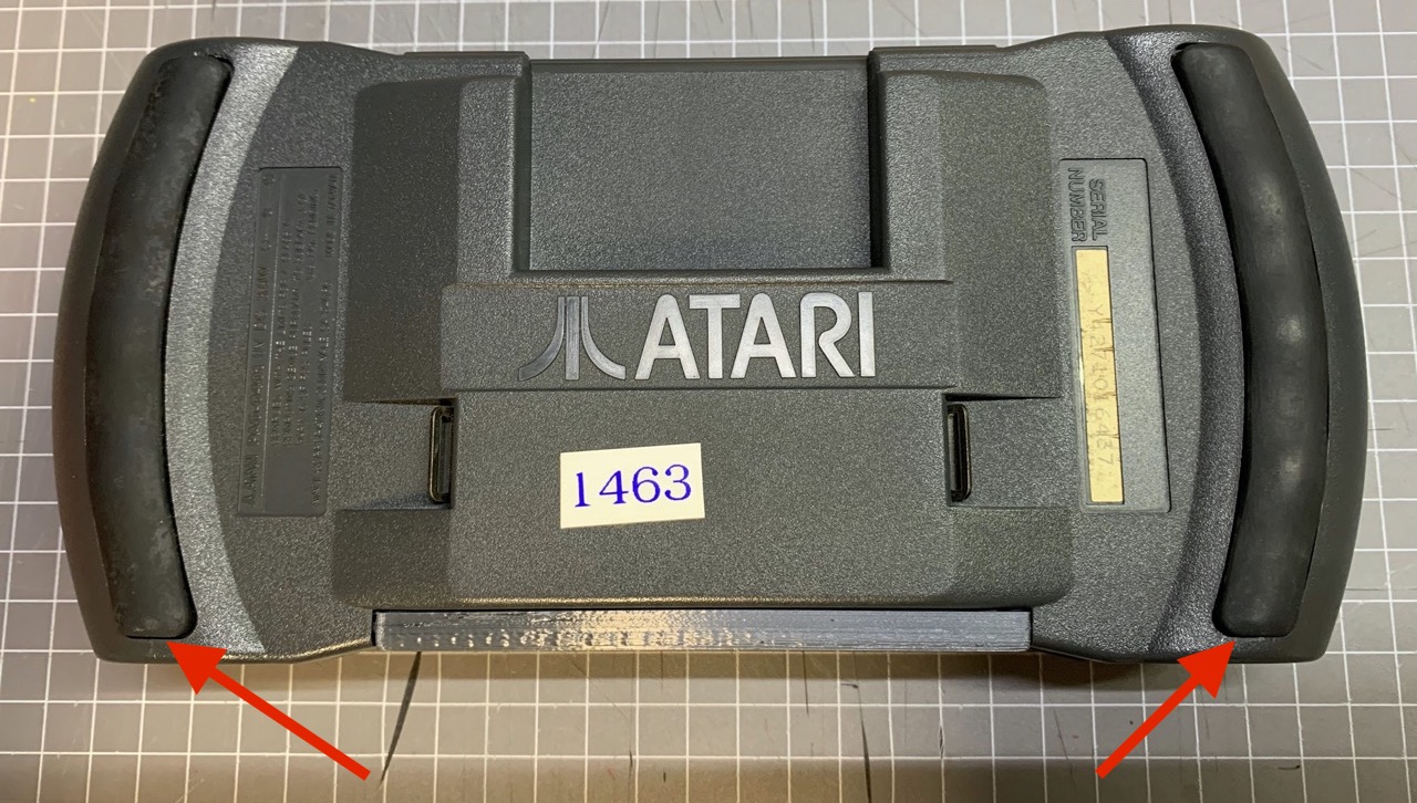
Step 1 - Wedge a flat screwdriver or a small spatula (preferable one made out of plastic) between the rubber hand-grips and the plastic case. There is a good amount of give in the rubber so you should be able to get something between it and the plastic fairly easily. The glue that is holding the grips down is very sticky but as soon as you can lift a few millimetres, the rest should come out without any issues.
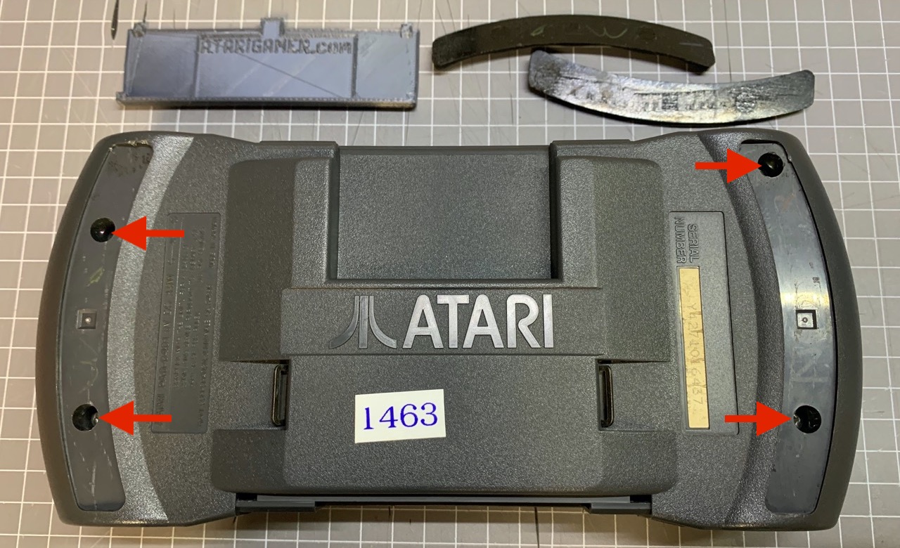
Step 2 - Take out the battery cover (we have a 3D printed replacement on our model Lynx) and then using a Phillips screwdriver, remove the four screws that were hidden under the rubber grips.
Step 3 - There are some plastic 'clips' on the two parts of the Lynx 2 case that hold the case together even without the need for screws. These are not usually very tightly bound. To separate the two halves of the case, it is easiest to start by uncoupling the clips around the battery compartment and moving around to the sides next. With a little bit of twisting, the two halves should come apart without the need to wedge a screwdriver between them.
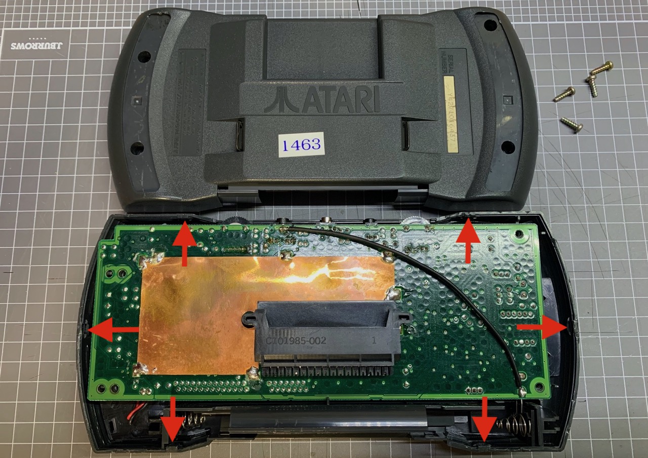
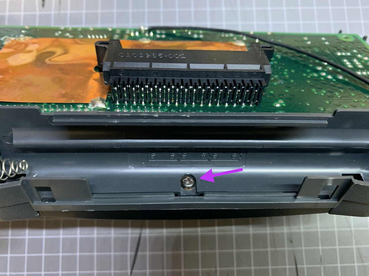
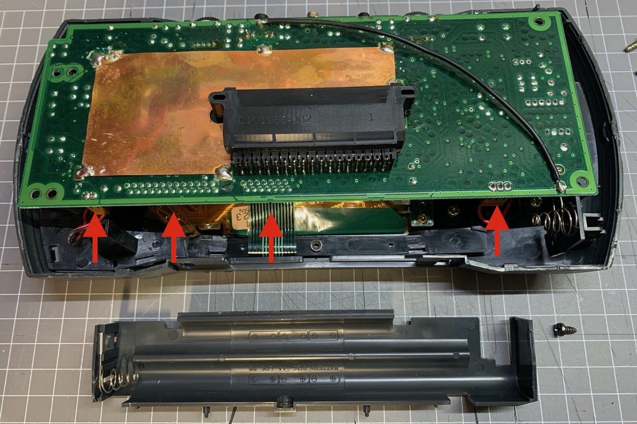
Step 4 - Remove the single screw that is holding the battery compartment in place. The compartment plastic can then be lifted out, you will need to lift the motherboard up slightly to give enough room for the spring side of the battery terminal to clear enough space.
Step 5 - Disconnect the speaker and screen back-light connectors next. These are the dark brown 2- and 3-pin connectors on the left and right side of the motherboard, respectively. Then disconnect the control membrane ribbon cable (grey) and the screen ribbon cable (orange). These ribbon cable are held in place with a locked socket, to unlock it, pull the top of the socket away from the motherboard - there are tabs on either side of the socket to help you do this. Once these are disconnected, the motherboard can be lifted out.
Step 6 - The screen and controller assembly are held in place by four and six screws, respectively. These are of different size. Unscrew these.
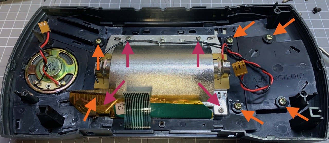
Step 7 - Lift out the screen, followed by the control assembly. The buttons and the controls membrane will lift out together with the assembly.
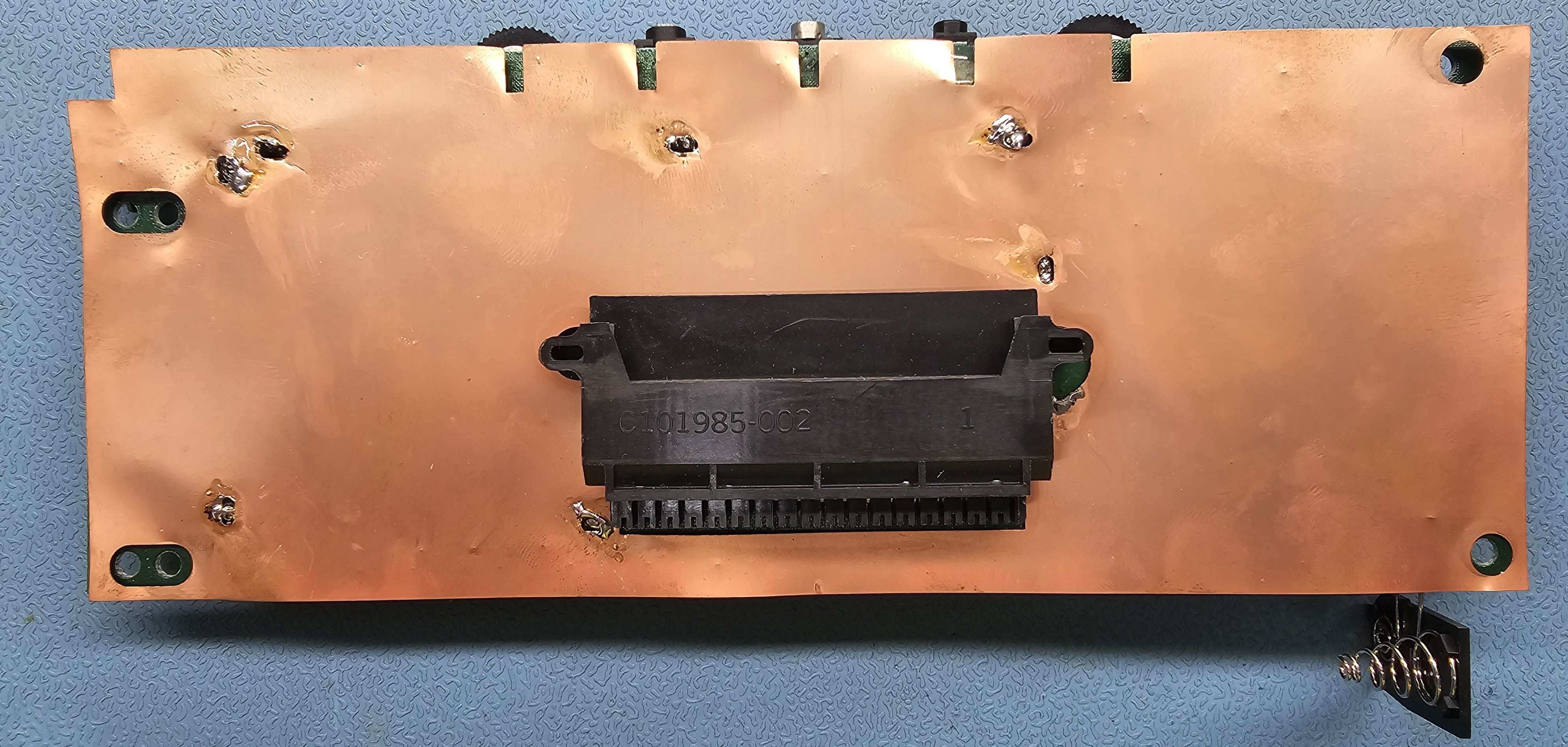
Note: Some Lynx motherboards had a full sized RF shield on the back. This shield can be removed if in the way of other work like recapping the motherboard. You will need to cut it around the cartridge connector, which ruins the shield, however there is little reason to keep it these days.
 ^
^
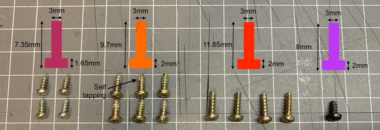
There are a total of 15 screws inside an Atari Lynx -
Each of the screws are 3mm in diameter but vary in length from 7.35mm to 11.85mm. Thread pitch appears to be similar on all. The controller assembly screws are self-tapping, the rest have a flat end. Apart from the screen screws, that have a 1.65mm thick head, the rest of the screws have a 2mm thick head. All screws are Phillips type.
This page is part of the Atari Lynx Repair and Troubleshooting Guides series.
^
♥ Did we get something wrong or you have something to contribute? Please tell us about it!
♣ We're looking for content editors and maintainers, if you want to help us out, let us know!