When we looked at the BennVenn LCD mod install, we also checked out and compared power usage of the original unmodded Lynx to the BennVenn and McWill LCD modded Lynx(es). The results were somewhat surprising, but that's probably because we didn't read this AtariAge thread. Atari Gamer reached out to Orange-Phantom to get permission to republish his findings from back in 2015 regarding power draw of the McWill modded Lynx vs the original, and he agreed.
So lets see how power hungry the McWill mod really is (spoiler alert - anyone claiming that it improves battery life is dreaming)...
 |
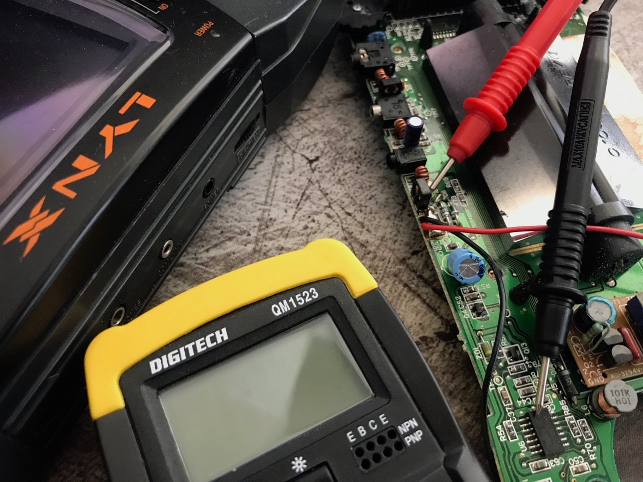
All voltages were supplied via the input jack, therefore the voltage supplied to the circuit board was 0.7 less due to the voltage drop of the inline silicone diode. Standby current of the modded Lynx II is 8.9ma at 7.9v (7.2v actual on the board). Standby current of the unmodded Lynx to is 0.001ma at 7.9v (7.2v actual on the board). The modded Lynx had both the McWill LCD mod and the 5V regulator circuit mod installed.
 A - Led is starting to blink (modded Lynx II) |
Orange-Phantom had the following to say...
So basically from these findings the modded Lynx II is drawing more power than an unmodded Lynx II. What is very clear though is how much better the old Lynx power circuit is on Batteries not only in it's lowest voltage in which it will allow the device to operate (although I don't know what the lowest voltage the McWill screen could operate at) but also the stand by current. I've had sets of Enloop rechargeable batteries run flat after 4ish days when my modded Lynx II has not been switched on and it's down to the way that Recom switching regulator is always powered on.
What is also clear by the measurements that I've taken is that the old Lynx II power circuit is a true high efficiency switching regulator circuit. The zener diode provides a voltage reference to the Hex Inverter which in turn high frequency switches the Q12 FET. This also explains why there is a 100uH choke (L15) after this FET. The FET is not just an on off switch. If you remove the zener diode then the hex inverter has no reference and thus stops switching the Q12 FET and you get 9V straight into your Lynx.
People in various forums have been stating that the "crappy" Zener diode is performing the actual power regulation in conjunction with the Q8 transistor. If this were the case then these components would have to be dissipating the voltage drop as heat, they run stone cold so they are not. Or put it another way, when people have bypassed the original circuit with a linear power regulator, they have to heat sink the linear power reg to dissipate the heat and yet the original Lynx power circuit requires no heat sinks and runs stone cold! The current draw vs voltage figures above are further proof that the original Lynx power circuit is a true high efficiency switching regulator.
These measured results are interesting to see and this is the second (or rather the earlier) proof of McWill LCD mod power draw inefficiencies. We still love this mod at Atari Gamer however, mostly for it's VGA output capability, so unless someone else can come along with a VGA - or better - a HDMI output mod for the Lynx, the McWill modded Lynx will be taking centre stage for big screen play. BennVenn's LCD mod of course takes first place if you are not interested in playing your Lynx on an external screen.
